USING PHOTO STITCHING SOFTWARE
Digital photo stitching software is the workhorse of the panorama-making process, and can range from providing a fully automatic one-click stitching, to a more time-consuming manual process. This is part 2 of the tutorial, which assumes all individual photos have already been properly captured (stage 1 below is complete); for stage 1 and an overview of the whole stitching process please visit part 1 of this tutorial on digital panoramas.
| Stage 1 | Equipment setup and acquisition of photographs |
| Stage 2 | Selection of desired photo alignment and input of camera and lens specifications |
| Stage 3 | Selection of perspective and projection type |
| Stage 4 | Computer shifts, rotates and distorts photos to conform with requirements of stages 2 and 3 |
| Stage 5 | Manual or automatic blending of seams |
| Stage 6 | Cropping, touch-up and post-processing |
TYPES OF STITCHING SOFTWARE
In order to begin processing our series of photos, we need to select an appropriate software program. The biggest difference between options is in how they choose to address the tradeoff between automation and flexibility. Generally speaking, fully customized stitching software will always achieve better quality than automated packages, but this may also result in being overly technical or time consuming.
This tutorial aims to improve understanding of most software stitching concepts by keeping the discussion as generic as possible, however actual software features may refer to a program called PTAssembler or PTGui (front-end for PanoTools or PTMender). PTAssembler incorporates a fully-automated one-click stitching option, in addition to providing for nearly all possible custom stitching options available in other programs.
At the time of this article, other notable programs include those that come packaged with the camera, such as Canon PhotoStitch, or popular commercial packages such as Autostitch, Hugin Panorama Photo Stitcher, Arc Soft Panorama Maker, Panorama Factory and PanaVue, among others.
STAGE 2: CONTROL POINTS & PHOTO ALIGNMENT
Panorama stitching software uses pairs of control points to specify regions of two camera photos that refer to the same point in space. Pairs of control points may be manually selected by visual inspection, or these may be generated automatically using sophisticated matching algorithms (such as Autopano for PTAssembler). With most photographs, best results can only be achieved with manual control point selection (which is often the most time-consuming stage of the software stitching process).
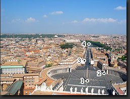
The example above shows a selection of four pairs of control points, for two photos within a panorama. The best control points are those which are based upon highly rigid objects with sharp edges or fine detail, and are spaced evenly and broadly across each overlap region (with 3-5+ points for each overlap). This means that basing control points on tree limbs, clouds or water is ill-advised except when absolutely necessary. It is for this reason recommended to always capture some land (or other rigid objects) in the overlap region between all pairs of photographs, otherwise control point selection may prove difficult and inaccurate (such as for panoramas containing all sky or water).
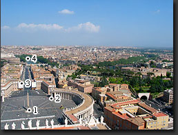
The example below demonstrates a situation where the only detailed, rigid portion of each image is in the silhouette of land at the very bottom—thereby making it difficult to space the control points evenly across each photo's overlap region. In these situations automated control point selection may prove more accurate.
PTAssembler has a feature called "automatically micro-position control points," which works by using your selection as an initial guess, then looking to all adjacent pixels within a specified distance (such as 5 pixels) to see if these are a better match. When stitching difficult cloud scenes such as that shown above, this effectively combines the advantages of manual control point selection with those of automated algorithms.
Another consideration is how far awayfrom the camera each control point is physically located. For panoramas taken without a panoramic head, parallax error may become large in foreground objects, therefore more accurate results can be achieved by only basing these on distant objects. Any parallax error in the near foreground may not be visible if each of these foreground elements are not contained within the overlap between photos.
STAGE 3: VANISHING POINT PERSPECTIVE
Most photo stitching software gives the ability to specify where the reference or vanishing point of perspective is located, along with the type of image projection.
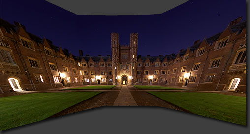
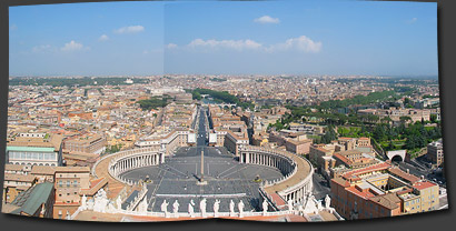
Careful choice of this vanishing point can help avoid converging vertical lines (which would otherwise run parallel), or a curved horizon. The vanishing point is usually where one would be directly facing if they were standing within the panoramic scene. For architectural stitches, such as the example below (120° crop from the rectilinear projection), this point is also clearly apparent by following lines into the distance which are parallel to one's line of site.
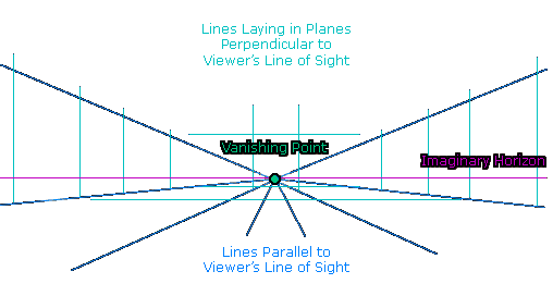
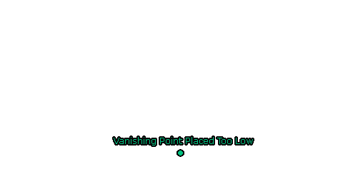
Incorrect placement of the vanishing point causes lines laying in the planes perpendicular to the viewer's line of site to converge (even though these would otherwise appear as being parallel). This effect can also be observed by using a wide angle lens in an architectural photo and pointing the camera significantly above or below the horizon— thereby giving the impression of buildings which are leaning.

move your mouse over the image to see image if vanishing point were too low
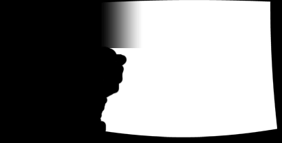
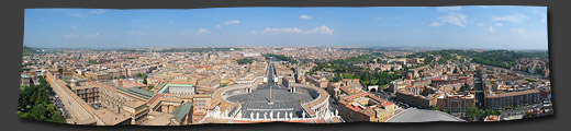
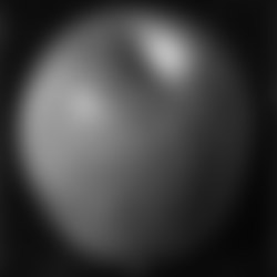
The vanishing point is also critical in very wide angle, cylindrical projection panoramas (such as the 360 degree image shown below). It may exhibit different looking distortion if misplaced, resulting in a curved horizon.
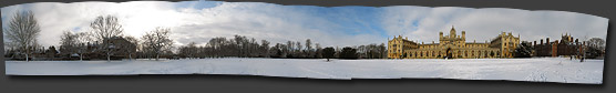

If the vanishing point were placed too high, the horizon curvature would be in the opposite direction. Sometimes it may be difficult to locate the actual horizon, due to the presence of hills, mountains, trees or other obstructions. For such difficult scenarios the location of the horizon could then be inferred by placing it at a height which minimizes any curvature.
Panorama stitching software also often gives the option to tilt the imaginary horizon. This can be very useful when the photo containing the vanishing point was not taken perfectly level. For this scenario, even if the vanishing point is placed at the correct height, the horizon may be rendered as having an S-curve if the imaginary horizon does not align with the actual horizon (in the individual photo).
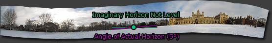
If the panorama itself were taken level, then the straightest horizon would be the one that yields a stitched image whose vertical dimension is the shortest (and is a technique sometimes employed by stitching software).
STAGE 4: OPTIMIZING PHOTO POSITIONS
Once the control points, vanishing point perspective and image projection have all been chosen, the photo stitching software can then begin to distort and align each image to create the final stitched photograph. This is often the most computationally intensive step in the process. It works by systematically searching through combinations of yaw, pitch and roll in order to minimize the aggregate error between all pairs of control points. This process may also adjust lens distortion parameters, if unknown.
 Yaw
Yaw
 Pitch
Pitch
 Roll
Roll
Note that the above photos are slightly distorted; this is to emphasize that when the stitching software positions each image it adjusts for perspective, and that the amount of perspective distortion depends on that image's location relative to the vanishing point.
The key quality metric to be aware of is the average distance between control points. If this distance is large relative to the print size, then seams may be visible regardless of how well these are blended. The first thing to check is whether any control points were mistakenly placed, and that they follow the other guidelines listed in stage 2. If the average distance is still too large then this may be caused by improperly captured images, including parallax error from camera movement or not using a panoramic head.
STAGE 5: MANUALLY REDIRECTING & BLENDING SEAMS
Ideally one would want to place the photo seams along unimportant or natural break points within the scene. If the stitching software supports layered output one can perform this manually using a mask in photoshop:
 |
||
| Without Blend | Manual Blend | Mask from Manual Blend |
Note how the above manual blend evens the skies and avoids visible jumps along geometrically prominent architectural lines, including the crescent of pillars, foreground row of statues and distant white building.
Make sure to blend the mask over large distances for smooth textures, such as the sky region above. For fine detail, blending over large distances can blur the image if there is any misalignment between photos. It is therefore best to blend fine details over short distances using seams which avoid any easily noticeable discontinuities (view the "mask from manual blend" above to see how the sky and buildings were blended).
On the other hand, manually blending seams can become extremely time consuming. Fortunately some stitching software has an automated feature which can perform this simultaneously, as described in the next section.
STAGE 5: AUTOMATICALLY REDIRECTING & BLENDING SEAMS
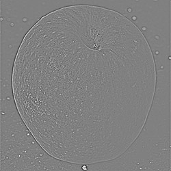
One of the best ways to blend seams in a stitched photograph is by using a technique called "multi-resolution splines", which can often rectify even poorly captured panoramas or mosaics. It works by breaking each image up into several components, similar to how an RGB photo can be separated into individual red, green and blue channels, except that in this case each component represents a different scale of image texture. Small-scale features (such as foliage or fine grass) have a high spatial resolution, whereas larger scale features (such as a clear sky gradient) are said to have low spatial resolutions.
 Original Image in Black and White
 Choose Processed Image:
| Large-Scale Textures | Small-Scale Textures |
The multi-resolution spline effectively blends each texture size separately, then recombines these to re-create a normal looking photograph. This means that the lower resolution components are blended over a larger distance, whereas the higher resolution components are blended over shorter distances. This addresses the common problem of visible jumps across the seams corresponding to smooth areas, or blurriness along the seams corresponding to fine detail.
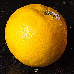
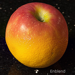
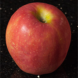
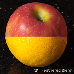
In the example below, we demonstrate a seemingly impossible blend between an apple and an orange—objects which contain different large-scale color and small-scale texture.
| Show: | Apple | Orange |
 Individual Images
| Show: | Feathered (Normal) |
Multi-Resolution Spline |
 Blended Image
Of course this "apples and oranges" blend would likely never be performed intentionally in a stitched photograph, but it does help to demonstrate the true power of the technique.
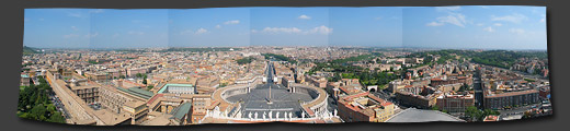
move your mouse over the image to see final blended result
The above example demonstrates its use in a real-world panorama. Note the highly uneven sky brightness at the seams, which was primarily caused by pronounced vignetting (light fall-off at the edges of the frame caused by optics). Move your mouse over this image to see how well the multi-resolution spline performs.
Smartblend and Enblend are two add-on tools that can perform the multi-resolution spline in PTAssembler and other photo stitching software. Smartblend has the added advantage of being able to intelligently place seams based on image content.
STAGE 6: FINISHING TOUCHES
Here one may wish to crop their irregularly shaped stitch to fit a standard rectangular aspect ratio or frame size. The assembled panorama may then be treated as any ordinary single image photograph in terms of post-processing, which could include photoshop levels or photoshop curves. Most importantly, this image will need an unsharp mask or other sharpening technique applied since the perspective distortion (using image interpolation) and blending will introduce significant softening.
For background reading on this topic, please refer to:
Part 1: Photo Stitching Digital Panoramas
or the tutorial on Understanding Image Projections